Laboratory
In order to measure the phenomena that we were interested in (see chapter The Filehne experiment). We created for the Perception group of the School of Psychology of Cardiff University a new audiovisual lab. In audio research, there is no standard measurement system but according to the needs we will give a priority to two main techniques:
Virtual Auditory Space vs Real Auditory Space
The VAS is the ability to create the illusion of any free-field environment using a closed-field sound system such as headphones or loudspeakers. This technique assumes that identical stimuli will be perceived identically at a listener’s eardrum whatever the physical mode of delivery. It is now accepted that the simulation of acoustical space is best achieved using closed-field systems since headphones allow a complete control over the signal delilvered to the listener’s eardrums. The disadvantage of this technique is that it requires compensation of the transfer function of the sound delivery system itself. Moreover, in order to give to the listener the perfect illusion of a 3D audio scene, you will need to use the binaural technique. To achieve that, it is necessary to recreate at each ear, the signals that would be perceived naturally. The use of the HRTF is the best way to reproduce the localisation cues needed.
Binaural broadcasting technique
The binaural synthesis is based on the use of the pair of binaural filters obtained from the HRTF. At each source position in the space \(r, \theta, \phi\) it exists a pair of HRTF, that we can obtain through a model or a set of measurements. In order to place a virtual source at a given position, it is necessary to find the pair of HRIR corresponding to the position in a database if available or calculate the interpolation and deduce a pair of binaural filters \(x_L\) and \(x_R\) adapted to the chosen implementation. For the headphone diffusion, the simplest way is to convolve the monophonic and anechoic signal \(x\) with each filter in order to obtain the signals \(x_L\) and \(x_R\) that will be broadcast on the headphones (see Fig. 21). In addition, it is necessary to compensate for the headphone that act as a filter.

Fig. 21 Binaural techique on headphones. After [Gui09].
The spectral filtering of a sound source before it reaches the eardrum is called the HRTF. The binaural HRTF can be thought of as a frequency-dependent and amplitude and time-delay differences that result primarily from the complex shaping of the pinnae. [Bat67] claimed that the folds of the pinnae cause time delays within a range of $0$ to \(300\mu\). This is a cause of a significant change in the spectral content at the eardrum. Because of the asymetric shape of the pinnae, this spectral changes vary with the source position. Moreover, the shape of pinnae differ from one subject to another. This means that in theory, we should measure the HRIR for an infinite number of positions in order to reconstruct perfectly the signal at the eardrums. Because it is impossible to measure an infinite number of points and because, measuring impulse responses of a subject is still nowaday is difficult and long task suggesting a sampling of a finite number position and then interpolate the missing positions. Another way is to use a bank a average HRTF and use the same bank for all subject. Both techniques bring artefacts once convolved with the signals. Results are localisation and externalisation of sounds problems. The externalisation problem is not still perfectly known. Nevertheless, [Gui09] suggested several possibilities that could have an impact on the externalisation such as the fact that the listener knows that signal is broadcast through the headphones, and feel the pressure of it on his ears. The absence of visual cues, or incoherent signals between the visual and audio modalities. The acoustics signals at the eardrums can be as well degrade due the the distortion brought by the headphones.
Multi loudspeakers technique
The use of loudspeakers instead of headphones avoid troubles about externalisation of the sound and a difficult HRTF measuring process. Spatialisation of sound is more robust, all spatialisation cues are naturally available and don’t need to be recreated. Nevertheless, several problems still exist such as the interpolation of sounds located between two speakers.
Todo
Becareful, in both cases (VAS and RAS), the interpolation is not a real problem for the simple reason that in VAS, we can’t measure an infinite number of points, hence, we will interpolate several positions. In RAS, we will not have an infinite number of speakers, thus, we will interpolate any position that is located between two speakers.
Equipment
Visual motion has been intensively investigated and need a quite standardised equipment (see [KB10][BJVDB01][Fre01]). Audio motion requires ad hoc systems and can differ a lot from one lab to another and will depend mainly on using VAS or RAS (Virtual Auditory Space vs Real Auditory Space) and many other parameters. The lab’s wiring diagram is given on Fig. 22 and a picture of the result is given on Fig. 23.

Fig. 22 Schematic of the lab audiovisual system. In green are represented the inputs, in brown the outputs.
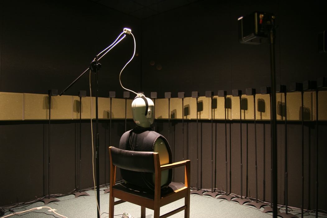
Fig. 23 Photo of the laboratory with a dummy head instead of a participant.
The room
is a parallelipedic shape with a superficy of \(13.76m^2\) (\(3.2 \times 4.3m\)). The lab has several characteristics such as:
- black walls in order to minimize light reflections,
- a proof-sound material on the wall to minimize acoustics reflections,
- no isolation from the outside noise.
A plastic rail surrounding the room at the ears heigh (when a participant is seated) has been covered with foam in order to reduce its impact on the acoustic. A measure of the RT gave a result of \(60ms\) on average. A measure of the noise floor has been done and gave a result of \(30\) dB on average with a pic around \(60\) dB at \(200\) Hz corresponding to the cooler system when it is turned on (see Fig. 24). Further investigation using acoustic antenna technique (such as beamforming or holography) would help to find where is the noise position and correct it in order to lower that noise. Because it is quite low frequency, it should not be perceived as a ponctual source by the participants and not interfere in the experiments.

Fig. 24 Noise floor of the laboratory with cooler system on.
Loudspeakers
For the broadcasting of the signal, we needed multiple loudspeakers using a RAS (see Virtual Auditory Space vs Real Auditory Space). Given the constraints we decided to use broadband speakers with a small size in order to have a quite high density. The system is composed of 24 Minx min 10, Cambridge Audio loudspeakers (see [Cambridge Audio11]). These speakers are passive and measure \(80 \times 80 \times 80mm\). The system uses \(22\) fixed speakers (with \(2\) speakers that can be placed where it is needed) along an hemicircle with a distance between each speaker of \(7.5^\circ\). As shown on the Fig. 25, the bandwith of the speakers is on average about from \(200\) Hz to \(10 000\) Hz. This is enough to use white noise in order to be able to use all acoustic available cues.

Fig. 25 Frequency response of the speaker 12 (placed @ \(0^\circ\)).
Amplifiers
Because we decided to keep amplifiers in the room, we needed a passive cooling system. We chose four \(6\) channels AMP-CH06, Auna amplifiers:
- Electric power: \(570\) Watts RMS,
- frequency response: \(20\) to \(20 000\) Hz,
- SNR: \(95\) dB,
- impedance: \(16~\Omega\).
Head tracking
In order to measure head tracking, we have two systems that is used according to the constraints of the experiment. A magnetic head tracker Flock of Birds, Ascension (see [Ascension04]) is used to record accurate head movements position and rotation in 3 dimensions. This tracker let us to record information in real time if it is needed to change the behavior of the experiment according to the head movements. If the participant can’t be aware of his head tracking, a webcam LifeCam HD 3000, Microsoft (see [Microsoft11]) fixed above the participant’s head on the ceiling is used to record and movement and is analysed afterwards. This system is less accurate and record only rotation in one dimension and position in 2 dimensions.
Video projector
In order to lead multi modalities experiments such as audiovisual experiments, a video project has been installed. Because of the room characteristics, a small and quiet projector were needed. A Qumi Q2, Vivitek (see [Vivitek13]) has been chosen and will be fixed on the ceiling above the participant’s head.
Sound card
for flexibility we used a 24~I/O, Motu DAC and a PCIexpress, Motu sound card (see [Motu13]). The sound card can handle up to \(4\) DAC (\(96\) channels) at \(24\) bits quantification and \(96\) kHz.
IT equipment
The computer is in a operating room next to the lab in order to minimise the acoustic impact. The main components of the computer are a i5-2400, Intel processor with \(3\) GB of RAM.
Softwares
Any software capable of using ASIO driver can be used to handle the high number of channels if there is no need of head tracking. Nevertheless, for the processing and for the experiments described in this document, Pure Data has been used to lead the experiments, Matlab, Mathworks or GNU Octave with the toolbox Playrec has been used for measurements or data analysis. The main advantage of using Pure Data is the real time processing and its capacities to handle the head tracker Flock of Birds, Ascension.
Loudspeaker compensation
As shown on Fig. 25, the response of the speaker is chaotic and because of its mechanic assembly, the frequency response will differ from one to the other. These differences can be heard by the participants and give them intrusive spectral or intensity cues that could bias the experiments. Because of the spectral response of the speakers, rather than trying to flatter it, it has been decided to bring the same default to every speakers. The speaker at \(0^\circ\) in front of the listener is the reference. The principle is to extract for each speaker impulse response the corresponding excitation pattern [1] (see equation (1)), get the spectrum difference from the reference excitation according to the current one and convolve the current impulse response with the spectrum difference.
Where \(p\) determines the shape of the pass band filter. \(g\) is the deviation in frequency from the filter center frequency divided by the center frequency.
Footnotes
| [1] | The excitation pattern is the distribution of internal excitation as a function of some internal variable related to frequency. |